Making an Arduino Based Levitron
Me and my college group made this machine for Physics Class, so I decided to show how we made it here. The final machine can levitate a magnet smoothly for days!
What the hell is Levitron?⌗
In short, Levitron is an electromagnet controlled by a micro-controller that “levitates” a permanent rare-earth magnet by alternating the coil current. If done quickly, it creates an illusion of levitation.
How it works?⌗
This Levitron uses a Hall Effect Linear Sensor to measure the magnetic field of the magnet by creating a voltage differential that is read by the Arduino. If the voltage is getting too high, this means that the magnet is getting closer to the coil, so the Arduino decrease the coil current. This makes the magnet fall with the gravity, and restart the cycle.
First Step: The Electromagnet⌗
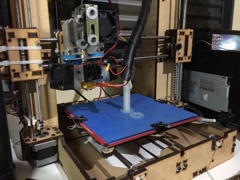
This is the main part of the project. The Electromagnet will generate the force we will need to pull the magnet in our direction. We used almost ~150 meters of 0.4 mm Copper Wire to make ~2000 turns in ~18 layers. This electromagnet is very strong, perhaps stronger than we need, so we will limit the max current to 1A@5V to prevent over-heating. In this case we 3D printed the reel.
Winding the coil will be the most tedious part of this project, but in the end you will have a very cool electromagnet! Thankfully Mateus made this for us with a screwdriver. Will be a good ideia to protect each layer with insulating tape to prevent any overlap. And remember to wind the wire always in the same direction.
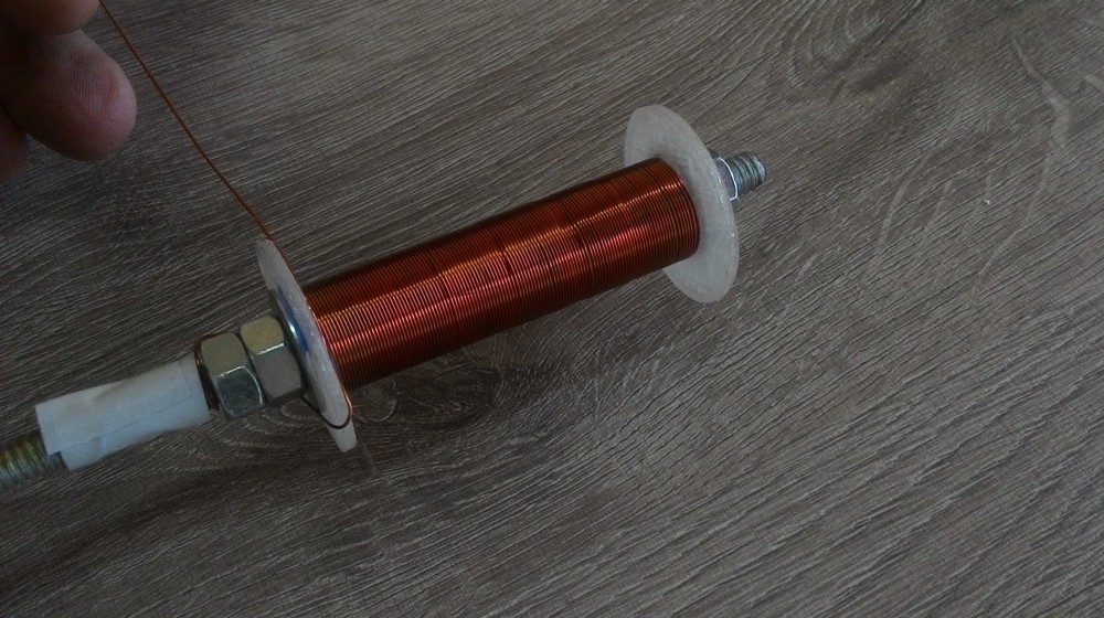
For the Ferromagnetic Core, we used a screw, but ideally it should fit perfectly inside the coil frame inner gap to generate the strongest magnetic field possible.
Second Part: Linear Hall Effect Sensor⌗
This is the second more important part of the entire project. This sensor provides the only information the Arduino needs to tune the frequency of the PWM Signal for a steady levitation. This sensor relies on a magical electromagnetic effect called Hall Effect, which translates the magnetic field strength to a differential electrical potential, which can be easily read by the Arduino analog port. In this project we used the SS49E Sensor, but any linear hall sensor will get the job done. Notice that some sensors have a Schmitt Trigger which translates the linear signal to PWM signal, making the sensor useless.
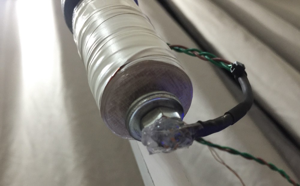
We made a 1CM dielectric separation between the sensor and the bolt with hot glue to prevent interference with the magnetic field created by the coil. This minor change will make the interference of the coil magnetic field insignificant, so that it can be safely ignored.
Third Part: The Circuit⌗
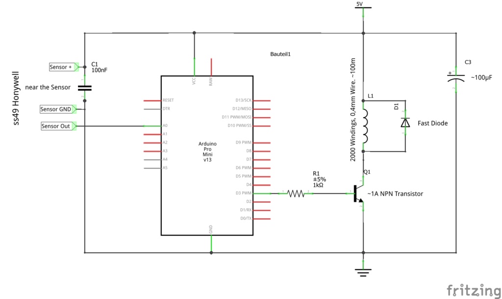
This is the most complex part of this project, below you can see the circuit diagram. The Arduino is wired with the Hall Effect Sensor thought a resistor. And the inductor have a flyback protection Diode (1N4148) to prevent the current generated by the magnetic field in the inductor fries everything. There is also an power LED indicator and N-Channel Transistor (IRF540) to handle the high current to the coil.
Fourth Part: The Code⌗
The code for this project is straightforward, you just need to say to the Arduino the equilibrium point of the magnet relative to the sensor readings. This is the only tuning you will need to do in this code.
After various tests we decided that a PID filter wouldn’t be necessary. Yeah, PID would make the levitation more smooth over time, but also would add unnecessary complexity and processing time in each loop. We also added a Software Low-pass Filter for give us more smooth reading from the Sensor.
#define sensorPin A0 // Hall Effect Sensor Pin
#define pwmPin 3 // Transisor Pin
int levitPoint = 690; // Levitation Point relative to the sensor readings

#define FILTER_SHIFT 4
int sensorValue = 0;
int deltaLevit = 15;
int maxL, minL;
int filter_input;
int filter_output;
long filter_reg;
byte induction = 128;

void setup() {
  pinMode(pwmPin, OUTPUT);

  // PWM Direct Controller (Note Below)
  TCCR2A = _BV(COM2A1) | _BV(COM2B1) | _BV(WGM20);
  TCCR2B = _BV(CS20);

  maxL = levitPoint - deltaLevit;
  minL = levitPoint + deltaLevit;
}

void loop() {
  filter_input = analogRead(sensorPin);

  // Lowpass Filter from http://www.edn.com/
  filter_reg = filter_reg - (filter_reg >> FILTER_SHIFT) + filter_input;
  sensorValue = filter_reg >> FILTER_SHIFT;

  if (sensorValue < levitPoint - 50) {
    induction = 255
  } else {
    if (sensorValue > maxL) induction = 0;
    if (sensorValue < minL) induction = 255;
    if (sensorValue <= maxL and sensorValue >= minL) induction = ((sensorValue - maxL)/5);
  }

  OCR2B = induction;
}
Note: This piece of code give us direct (and faster) access to the hardware PWM pin of the ATmega, this tiny hack is well documented here.
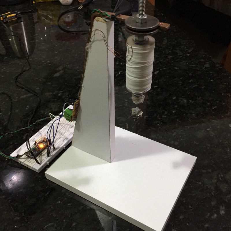
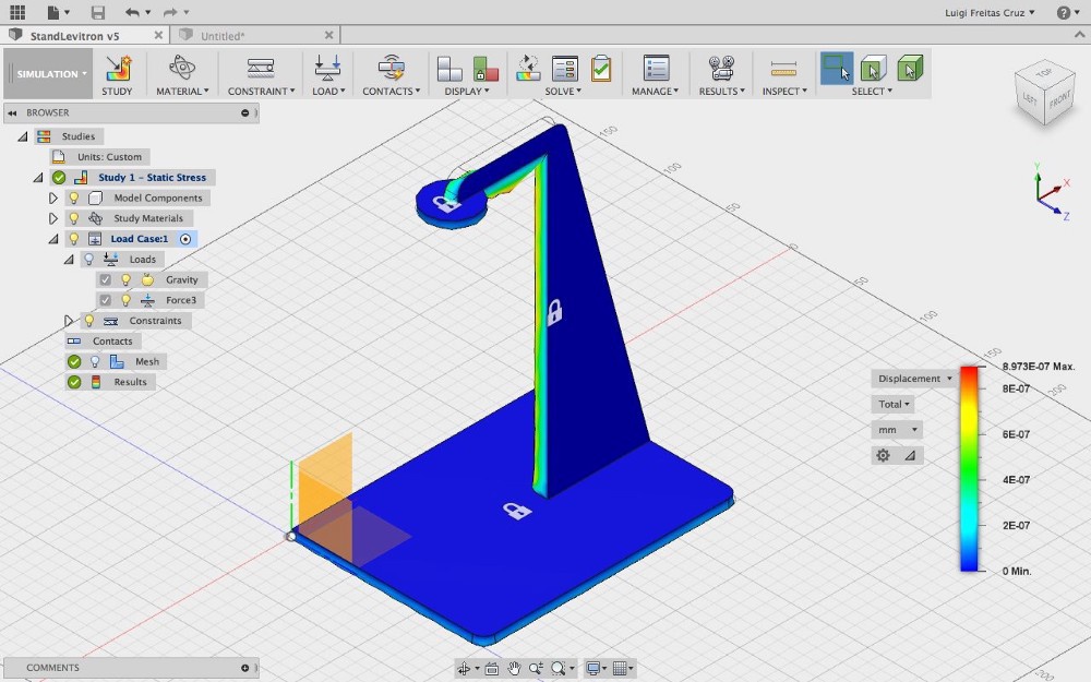
Final Part: The Frame⌗
In this part you can do whatever you want, we made a wood frame to secure the coil in place, but it can be made out of any material, acrylic for example.
Appendix: Next Up⌗
In the near future I will add a serial feedback to MATLAB for educational purposes. Would be great to have a realtime plot to see how the magnetic field and PWM signal varies as the magnet moves and levitates.